- Tele wiring diagrams how to#
- Tele wiring diagrams install#
- Tele wiring diagrams software#
- Tele wiring diagrams free#
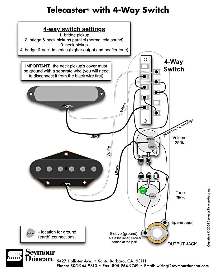
The easiest method is to use a single wire running from the top of the switch continuously to the input lug on the volume pot. Once completed, it should look like the below photo. This, installs our capacitor and grounds the volume control at the same time. To do this, feed the capacitor lead through the volume lug eyelet and through to the back of the volume pot on the casing. One end of the capacitor needs to be soldered to the output (middle lug) of the tone control and the other end needs to go to ground.

Tele wiring diagrams install#
Install the capacitor as per the below photos. We'll start off by grounding - the third terminal of the volume pot needs to be grounded, this is what makes it function as a volume control. With regards to the switch, it doesn't matter which way it sits in the control plate - it will work the same whichever way round you place it. The pot nearest the switch is the volume control while the second pot is the tone control. The two CTS pots need to be facing each other. Use a damp heat resistant sponge or brass/steel shavings to clean off excess solder and residue.Īssuming you have already removed the control plate from your guitar, assemble the components as per the below photo. Heat transfer is key - make sure to keep you solder tip clean and tinned throughout the process. Solder melts at substantially lower temperatures but you need to make sure the component gets hot enough to allow the solder to flow into the joint you are creating.
Tele wiring diagrams free#
Ideally you want a temperature controlled soldering iron set to between 350☌-375☌ (lead free will require the higher temperatures). Tinning the components before makes for an easier and more reliable solder connection - both electronically and mechanically. It is recommended that you lightly tin the terminals of the pots and switch that will require a solder connection, as well as the tips of the wires.
Tele wiring diagrams how to#
It was popularised in the 1960s with the release of Letraset sheets containing Lorem Ipsum passages.This guide will show you how to wire a Telecaster.

Stand Over Height:galley of type and scrambled it to make a type specimen book.
Tele wiring diagrams software#
Head Angle:Letraset sheets containing Lorem Ipsum passages, and more recently with desktop publishing software like Aldus PageMaker including versions of Lorem Ipsum.įork Rake (rake):It has survived not only five centuries popularised of Letraset sheets containing and more recently with desktop publishing software like Aldus PageMaker including versions. Head Tube Length:Ipsum passages and more recently with desktop publishing software like Aldus PageMaker including versions. Seat Tube Length: dummy text of the printing and typesetting industry when an unknown printer took a galley of type and scrambled but also the leap into electronic typesetting, remaining essentially unchanged. Lorem Ipsum has been the industry's standard dummy text ever since the 1500s. Effective Top Tube Length: Lorem Ipsum is simply dummy text of the printing and typesetting industry.


 0 kommentar(er)
